Architecture
Overview
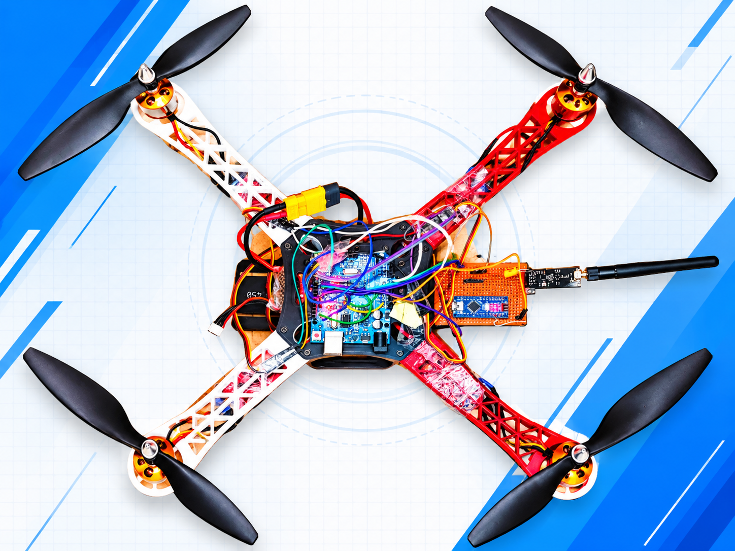
This project takes a pile of loose parts to a bench-verified quadcopter: a hand-built 6-channel Arduino remote, a matching nRF24L01 receiver, and an Arduino Uno flight controller with an MPU-6050 gyro that drives four brushless motors.
It is written as a bring-up log, not just a wiring diagram. Every stage has a small test sketch, an expected result, and the real errors I hit along the way.
What you will learn
- How a 2.4 GHz nRF24L01 radio link carries six stick, switch and knob channels
- How to prove each part works before you connect the next one
- How a receiver's servo-style pulses feed a flight controller
- How to calibrate the flight controller and check motor directions safely
Who this is for: builders comfortable with Arduino sketches and basic wiring. Difficulty is Advanced because it involves a LiPo battery, ESCs and spinning motors.
What this is not: it is not a from-scratch flight controller. The stabilisation firmware is the community YMFC-AL flight controller by Joop Brokking (www.brokking.net). It is not included here — you download it from its author. This project covers the radio side, the test tooling, the wiring, and the debugging that gets that firmware running with a DIY receiver.
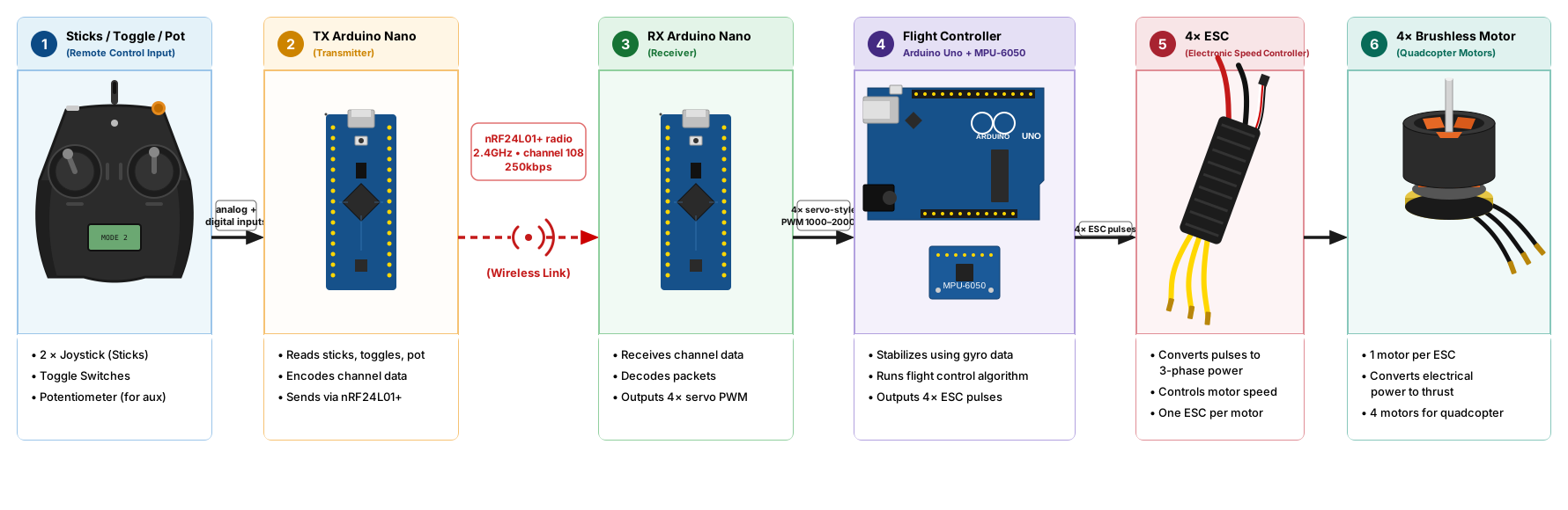
In words: the remote reads your controls and sends them over the radio. The receiver turns them back into normal RC pulses. The flight controller reads those pulses, measures how the frame is tilting with the gyro, and adjusts the four motors many times a second to keep the drone stable.
How the radio link works
- Radio: nRF24L01+ at 2.4 GHz, channel 108, 250 kbps, CRC-8, maximum power, same address on both ends.
- Auto-acknowledge is OFF in the flying configuration. The remote streams packets one way and does not wait for a reply. The link-check sketches turn it ON temporarily, only as a diagnostic.
- Each packet is 6 bytes (0–255 each): throttle, yaw, pitch, roll, aux1, aux2.
- The receiver converts each byte to a 1000–2000 µs pulse with the Servo library — the same signal a hobby receiver produces.
- Failsafe: if no packet arrives for about 1 second, the receiver sets throttle to about 1047 µs and re-centres the sticks near 1500 µs.
Channel map
- CH1 roll: right stick X → remote A3 → receiver D9
- CH2 pitch: right stick Y → remote A2 → receiver D2
- CH3 throttle: left stick Y → remote A0 → receiver D3
- CH4 yaw: left stick X → remote A1 → receiver D4
- CH5 aux1: toggle → remote D2 → receiver D5
- CH6 aux2: potentiometer → remote A7 → receiver D6
Only CH1–CH4 go to the flight controller. CH5 and CH6 are free for extras.
FAQ
Can I use an Arduino Uno for the remote? Yes. A7 does not exist on the Uno, so move AUX2 to A5. A ready-made variant is in the downloads.
Why is auto-acknowledge off? The remote streams one-way without waiting for replies, which keeps latency low. Turn it on only for diagnostics.
Can I use this receiver with Betaflight or iNav? Not directly. It outputs six separate PWM signals, while those flight controllers expect one wire (PPM, SBUS and similar). A PPM-output version of the receiver would be the next step.
Can I use a 4S battery? Not with this build. The battery-voltage divider and the firmware are set up for 3S.
Do I need the throttle stick "down" to be the lowest value? Yes. Throttle fully down must read below 1050 µs at the flight controller, or the drone will not arm.
Watch the build
Components & parts
| Part | Qty | Price | ||
|---|---|---|---|---|
Arduino NanoATmega328P, CH340, headers soldered — Transmitter | 1 | ₹310 | Buyad | |
2-Axis Joystick ModuleAnalog thumb joystick | 2 | ₹180 | Buyad | |
10K PotentiometerRotary, with knob | 1 | ₹140 | Buyad | |
Mini Toggle Switch SPDTARM and MODE switches | 1 | ₹130 | Buyad | |
Rocker SwitchMain power on/off | 1 | ₹120 | Buyad | |
Tactile Push ButtonsRoll/pitch/yaw trims | 6 | ₹130 | Buyad | |
2S LiPo 7.4V500–1000 mAh — Transmitter battery | 1 | ₹550 | Buyad | |
5mm LED + 330Ω ResistorPower indicator | 1 | ₹120 | Buyad | |
Perfboard or EnclosureTo mount everything | 1 | ₹150 | Buyad | |
Arduino Nano (Receiver)Same as the transmitter — on the drone | 1 | ₹310 | Buyad | |
Male Header Strip 2.54mm3-pin output header for the 6 channels | 1 | ₹120 | Buyad | |
NRF24L01+ PA+LNA with SMA AntennaLong-range version — one for each side | 2 | ₹420 | Buyad | |
NRF24 3.3V Adapter BoardSocket adapter with onboard regulator | 2 | ₹150 | Buyad | |
Electrolytic Capacitor 100–470µFOne across VCC–GND on each radio | 2 | ₹110 | Buyad | |
F450 Frame with Integrated PCBBottom plate doubles as power distribution | 1 | ₹850 | Buyad | |
A2212 1400KV Motors + 30A ESCs + 1045 PropsCombo set of 4 | 4 sets | ₹3,450 | Buyad | |
Spare 1045 Props (CW + CCW)You will break some | 2–3 pairs | ₹150 | Buyad | |
3S LiPo 11.1V2200–3800 mAh, 20C or higher, XT60 | 1–2 | ₹1,480 | Buyad | |
Arduino UNO R3Flight controller in the YMFC-3D schematic | 1 | ₹490 | Buyad | |
MPU-6050 (GY-521)Gyro and accelerometer | 1 | ₹220 | Buyad | |
Resistors 330Ω, 1kΩ, 1.5kΩLED and battery voltage divider | 1 each | ₹140 | Buyad | |
1N4001 DiodeD1 on the schematic | 1 | ₹100 | Buyad | |
XT60 Connector PigtailBattery to frame | 2 | ₹190 | Buyad | |
LiPo Balance Charger (iMAX B6 type)Essential — nothing else charges the 3S pack safely | 1 | ₹1,550 | Buy | |
LiPo Safe BagFire-safe charging and storage bag | 1 | ₹290 | Buy | |
LiPo Voltage Alarm (1–8S)Low-voltage buzzer alarm | 1 | ₹230 | Buy | |
Battery StrapHolds LiPo to the frame | 2 | ₹150 | Buy | |
Dupont Jumper WiresMale-female assortment | 1 set | ₹210 | Buy | |
Soldering Iron Kit, Heat Shrink, Zip TiesBasic soldering setup | 1 | ₹430 | Buy | |
MultimeterDigital multimeter for debugging | 1 | ₹250 | Buy | |
Vibration Damping Foam for MPU-6050Isolates gyro from motor vibrations | 1 | ₹180 | Buy | |
| Core build total (required parts): | -- | |||
| Total of checked items: | -- | |||
Links marked "ad" are affiliate — we may earn a small commission at no extra cost to you.
Wiring & connections
| From | To |
|---|---|
| nRF24 Adapter VCC | 5V |
| nRF24 Adapter GND | GND |
| nRF24 Adapter CE | D7 |
| nRF24 Adapter CSN | D8 |
| nRF24 Adapter SCK | D13 |
| nRF24 Adapter MOSI | D11 |
| nRF24 Adapter MISO | D12 |
| Left stick Y | A0 |
| Left stick X | A1 |
| Right stick Y | A2 |
| Right stick X | A3 |
| Toggle switch | D2 |
| Potentiometer wiper | A7 |
| Receiver D9 | FC Pin 8 |
| Receiver D2 | FC Pin 9 |
| Receiver D3 | FC Pin 10 |
| Receiver D4 | FC Pin 11 |
| Receiver GND | FC GND |
| MPU-6050 SDA/SCL | Uno A4/A5 |
| Status LED | Pin 12 |
| Battery voltage | A0 |
Step-by-step build
Is each nRF24 module alive?
Is each nRF24 module alive?
Flash NRF_TX_test on one Nano and NRF_RX_test on the other. Open the receiver's Serial Monitor.
- Pass: "Module OK" at boot, then a counter climbing: Received #0, #1, #2...
- Fail: "begin() failed" or "chip not connected" means power or SPI wiring. Check the 5 V feed, the six signal wires and the capacitor.
- Keep the boards 1–2 m apart; PA+LNA modules can overload each other point-blank.
Does every control on the remote work?
Does every control on the remote work?
Flash Transmitter_RemoteTest. Move every stick, flip the toggle, turn the pot.
- Centred sticks read about 500 raw and about 128 sent. Full travel reaches about 0 and 255.
- The toggle flips OFF and ON cleanly. The pot sweeps smoothly.
- The first field shows TX:on when the radio is detected and TX:OFF when it is not.
- If the toggle flickers, wire it firmly between D2 and 5 V/GND.
Do the two radios really hear each other?
Do the two radios really hear each other?
Flash TX_LinkCheck on the remote and RX_LinkCheck on the receiver, keep them 1–2 m apart, and watch the remote's monitor.
- ACK:YES means the receiver is heard. The link is good.
- RADIO: NOT DETECTED means the remote's own module has a power or wiring problem.
- TX:on | ACK:no means the remote is fine but the receiver is not powered, not wired, or not listening.
Receiver and servo outputs
Receiver and servo outputs
Flash Receiver_Test on the receiver Nano. It prints every channel and drives six servo outputs at the same time.
- LINK:OK with numbers moving means packets are arriving.
- Plug a servo into the receiver's pin for the channel you are moving (D3 for throttle, etc.). Signal to the pin, + to 5 V, - to GND.
- Failsafe test: switch the remote off. Within about a second the monitor shows LINK:LOST and throttle drops to about 1047 µs.
Motor directions
Motor directions
Flash Motor_Direction_Test_UNO. ESC signals go to D3, D5, D6 and D9, with grounds shared with the Uno. Bolt the motors down and keep the ESCs' 5 V wires unplugged from the Arduino.
- It arms the ESCs, ramps all four motors from 0 to 50 %, holds, then ramps down.
- Compare each motor with the directions above. Wrong way? Power off and swap two motor wires.
Receiver into the flight controller
Receiver into the flight controller
Wire the receiver to the flight controller and flash FC_Receiver_PinTest on the Uno.
- Pass: P8, P9, P10 and P11 all show about 1000–2000 and move with the sticks.
- 0 on a pin means nothing arrives there: a loose wire, a missing common ground, or a receiver stuck on LINK:LOST.
Is the gyro found, and which ID does it report?
Is the gyro found, and which ID does it report?
Flash I2C_Scanner, then MPU_WhoAmI.
- The scan should find a device at 0x68.
MPU_WhoAmIprints the chip's ID. A genuine MPU-6050 answers 0x68. Many modules sold as MPU-6050 answer 0x70 — a compatible MPU-6500-class chip.- Nothing found: check SDA/SCL, VCC (5 V on a GY-521) and GND.
Setup, ESC calibration and flight code
Setup, ESC calibration and flight code
Upload the three YMFC-AL sketches in this order: setup → ESC calibration → flight controller.
8a. Setup: Checks I2C, waits for receiver pulses, asks you to centre/move sticks, calibrates gyro (keep still!), and measures angles.
8b. ESC calibration: Passes throttle straight to ESCs to learn endpoints.
8c. Flight code: Arm by moving throttle down and yaw left. Disarm with throttle down and yaw right.
Bench arm test, then first flight
Bench arm test, then first flight
Go through the First-flight checklist. Always test arming and disarming without propellers first.
- Low hover only initially, small stick movements, gentle landing.
- If it tips or lunges, cut throttle and disarm instantly.
Code
Troubleshooting
ERROR 3, no gyro found
TX:OFF, radio not detected
LINK:LOST while the remote is on
Numbers change but the servo does not move
Random LINK:LOST when servos move
YMFC ERROR 1, no valid receiver signals
ERROR 4, no angular motion detected
ERROR 6, receiver channel verification failed
ERROR 8, I2C clock not 400 kHz
License & credits
License: MIT
This page contains affiliate links (marked "ad"). We may earn a commission — it never costs you extra.